MineRad

A Ground Penetrating Radar for Landmine Detection
 
 
System Info
 

 WB00882_.gif (970 bytes)Background

 
Ground Penetrating Radar has been identified as one of the more promising technologies for the detection of non-metallic landmines. The term Ground Penetrating Radar refers to a range of electromagnetic techniques designed with the goal to detect and locate objects or interfaces buried beneath the earths surface [Daniels:95]. 

The GPR community has seen the development of two distinct techniques, namely Pulse or Impulse Radar and Stepped Frequency Continuous Wave (SFCW) Radar.  While the latter technique has been investigated since 1972, it is Pulse Radar which has dominated the GPR industry. This was due to the high cost and complexity of SFCW GPR. Over the last decade the cost of RF technologies (fast switching synthesizers) has decreased considerably, making it more feasible to develop SFCW GPR. In addition the availability of fast, low cost digital signal processors has contributed to the growing interest in this implementation of a subsurface radar 

The University of Cape Town has been involved in GPR research for the past six years - researching and developing new and novel hardware architectures and signal processing techniques - with the primary focus on Landmine Detection.


WB00882_.gif (970 bytes)System Description

 
MineRad is a 900MHz to 2.1GHz Stepped Frequency Continuous Wave Ground Penetrating Radar designed for landmine detection. It is been developed at ESD Reunert Defence in conjunction with the University of Cape Town 

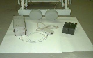
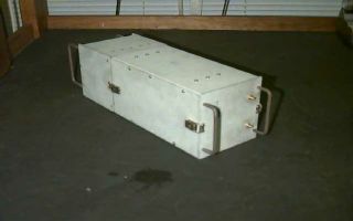
The radar consists of a radar transciever connected to a Laptop PC via fibre optic cables. (See Figure 1). The radiators  used are circularly polarised wide band antennas in a bistatic configuration. The radar transciever  integrates a RF transmitter and receiver, digital controller and processor and a DC-DC . The radar parameters are listed in the Table 1 below.

Figure 1: Radar Hardware

Table 1: Radar Parameters

Bandwidth 900MHz to 2100MHz
Frequency Resolution 1MHz
Number of Steps 1200
Transmit power 18dBm  (max)
Receiver Dynamic Range 72dB  (90dB with stacking)
Antenna Polarization Circular (LHC,RHC)
Radar Processor Pentium Laptop
Power consumption 12W
 
Figure 2: Radar transceiver

WB00882_.gif (970 bytes) Radar Measurements

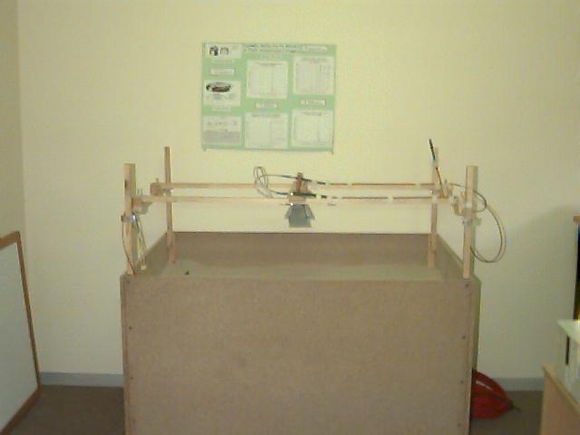
Figure 3 (picture on the top left) shows the measurement setup used to test the radar. It consists of a 1.5m (l) x 1m(w) x 1.2m(h) sandbox situated in the corner of my office. Various targets have been buried at various depths in the sandpit and imaged with the radar.  Figure 3: Measurement sandpit
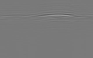
Figure 4 (picture on the bottom left) shows the radar image for a small metal ball buried at 10cm below the sand surface. This image was taken from the display of the radar data capture software. Figure 4: 2D radar intensity plot of the metal ball at 10cm below the surface
 
 
WB01722_.gif (138 bytes)Back to MineRad Home Page 
WB01722_.gif (138 bytes)Back to the LDRG Home Page WB01722_.gif (138 bytes) Back to the RRSG Home Page WB01722_.gif (138 bytes) Back to the UCT Home Page


This page was last modified on Tuesday,December, 1998 by Alan Langman